

Description
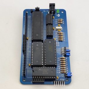
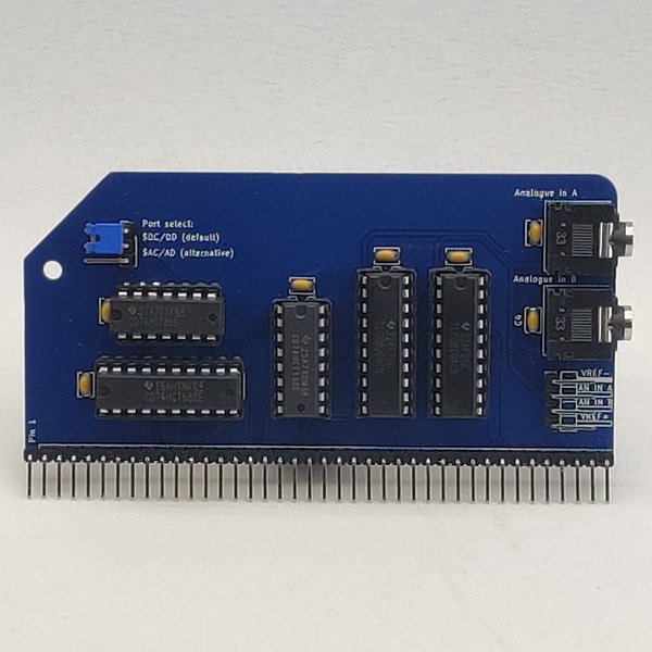
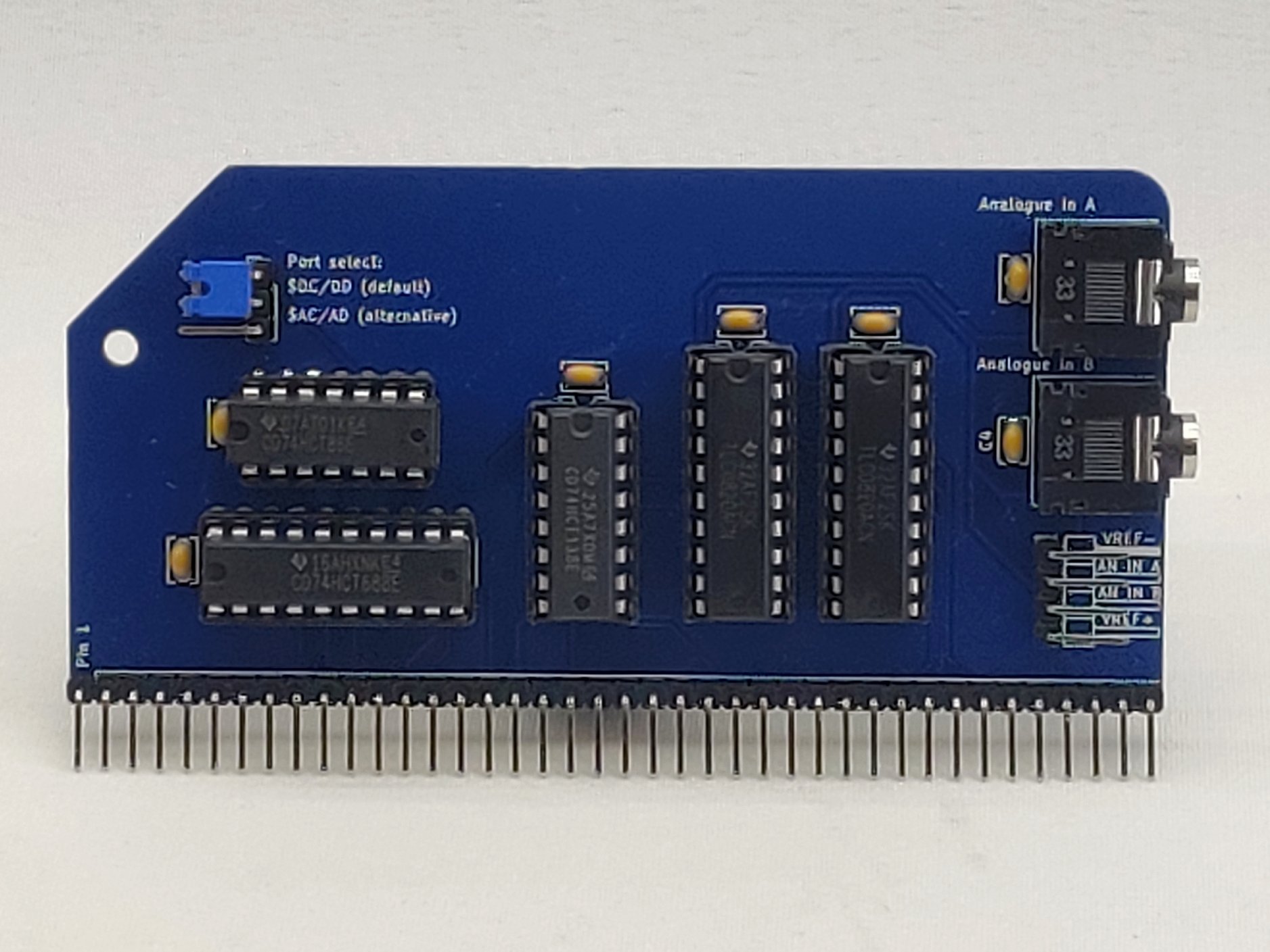
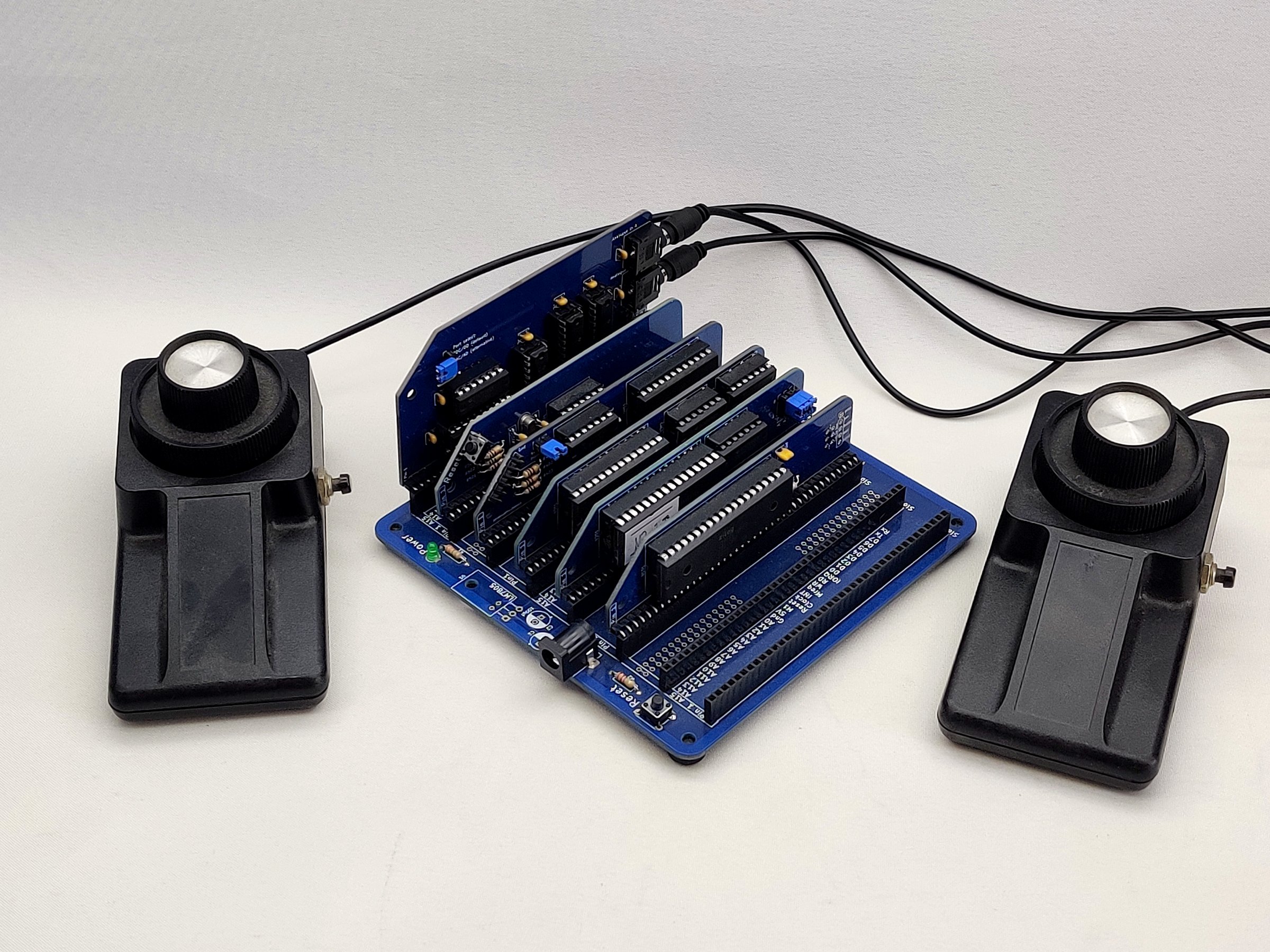
The Dual Paddle Analogue Module from Peacock Media features two TLC0820 analog to digital converters. These ADCs give 8 bit resolution of voltages between 0 to 5v and can be easily read by the RC2014. Input is via 3.5mm TRS (headphone) jacks, or a 4 pin 0.1″ header. It is compatible with all models of RC2014 from the RC2014 Micro to the RC2014 Zed Pro.
Connecting to the ports
There are two analogue inputs, a common ground and a reference 5v. These are available on header pins or two 3.5mm TRS jacks.
Jacks were chosen so that you can build an input device such as a paddle and then simply plug it in without worrying about which connection is which.
Tip: 5v reference voltage
Ring: analogue input
Sleeve: ground
Important : The analogue inputs are not tolerant of voltages above the 5v reference, or below ground.
The best ways to use this are:
- a potentiometer dividing the 5v and ground
- a circuit which uses the 5v and ground for its supply
In these cases it’s not possible to go outside these limits.
It is possible to measure an outside signal using only the analogue input and the ground, but you must take care that the signal doesn’t exceed 5v. Ideally, build in your own clamping / protection.
Port addresses
Port A and port B have consecutive addresses. The default ports are $DC/$DD (220/221 decimal). You can use the jumper to switch to the alternative addresses $AC/$AD (172/173). This fits with recent official RC2014 products such as the LCD Driver, Why Em-Ulator and SID-Ulator.
If you need an alternative to those options, use the solder pads on the back of the board, JP2 (cut between the left two and bridge the right two). This will allow you to use $5C/$5D or $2C/$2D.
Reading the ports
You can read the ports in any language and it’s as simple as using an input instruction. Or maybe two.
The analogue to digital converters (ADCs) use a two-step process. First you have to prompt the chip to read the analogue input and latch the result. Let’s call that the ‘refresh’. Then after a suitable delay you can read the result. The chip works very quickly but it’s not possible to guarantee that the new data is available during a single input instruction at the regular cock speed of the RC2014.
It might seem natural to make the first step an output to the port and the second step an input. However, I’ve chosen to do both operations in a single input, for reasons that will shortly be clear.
This means that depending on your program loop, you may want to read the port twice:
BASIC
20 INP(&HDC) : REM trigger a refresh

30 LET A=INP(&HDC) : REM A is now a value between 0 and 255
C
inp(0xDC); // trigger a refresh

uint8_t a = inp(0xDC); // possibly z80_inp() depending on compiler and libraries
assembly
ld c,$dc

in a,(c) ; trigger a refresh

in a,(c) ; a now contains a value between 0 and 255
However (and this is the reason for the design decision) if you are writing a very tight loop for the fastest possible sampling (eg sampling an audio signal) then you will only need to make a single input instruction within your loop. That instruction will read the available data as well as triggering the refresh for the next loop. Here is the sampling loop in the ‘ohsillyscope’ audio sampling example:
// collect 256 bytes of data into array d[ ] - tight loop

for (int x=0; x<256; x++) {

//wait(1); // use a delay for a lower sample rate

d[x]=inp(0xDC);

}
Tip: The first input may not give meaningful data, so you may want to make a dummy input before you enter your loop.
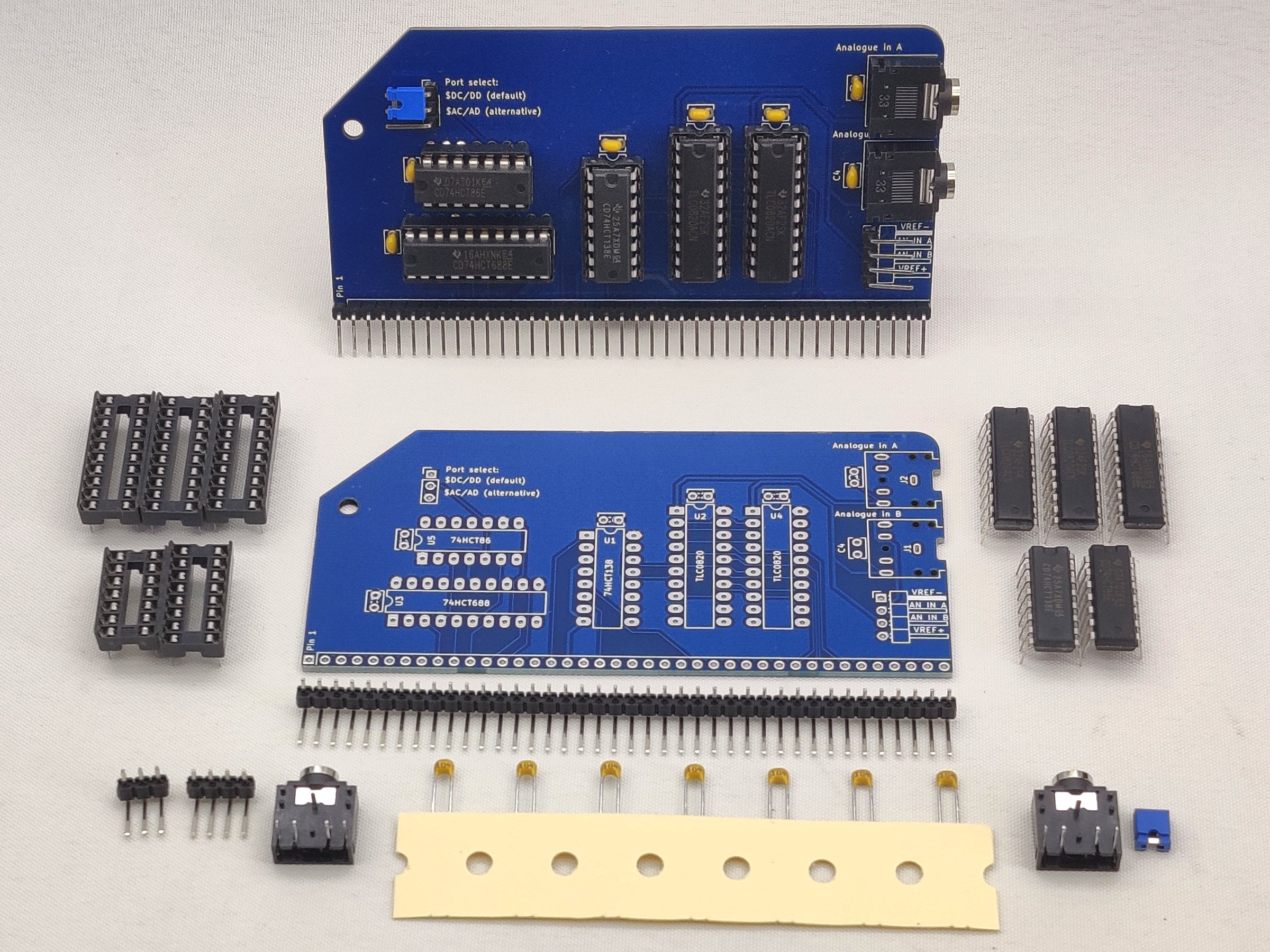
Note that the Dual Paddle Analogue Module kit includes all the parts needed to build the kit, however, it does not include any paddles or other input circuitry
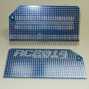
For PCB Only option, see Expansion Module PCB listing