Description
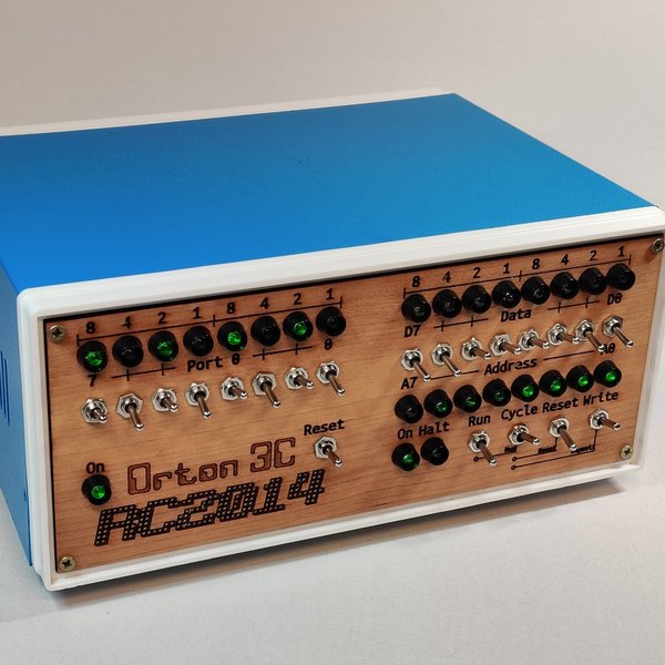
The Universal Front Panel I/O Kit allows you to add a RomWBW front panel to any enclosure. It can also be used to add I/O to the RC2014 Orton 3C computer. The kit is made up of two parts, the I/O Panel and the I/O Module. For RomWBW computers, red LEDs with chrome bezels and 1k resistors should be used. To match the Orton 3C, high intensity green LEDs with black bezels and 22k resistors should be used.
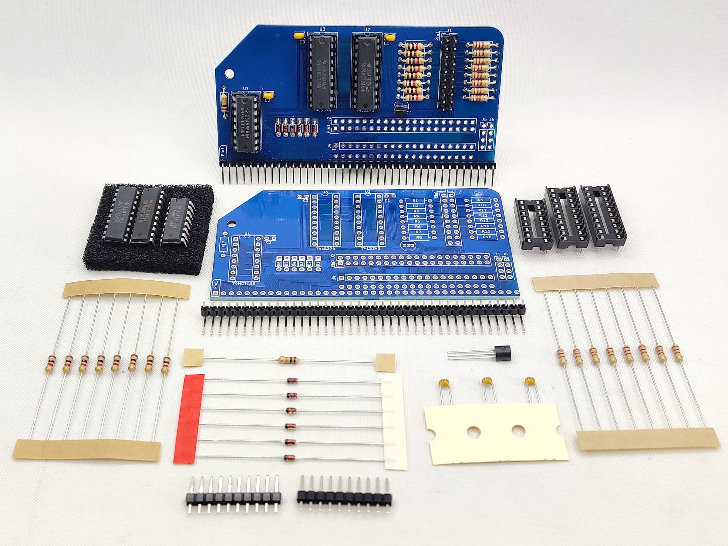
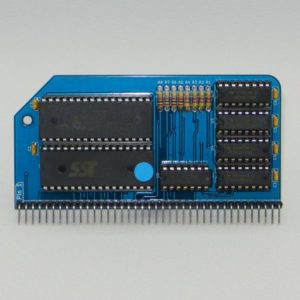
The Front Panel I/O Module sits in your RomWBW enabled RC2014 and provides 8 input and 8 output lines on port 0. It is compatible with the RC2014 Zed and RC2014 Zed Pro, or any RC2014 fitted with a 512k ROM 512k RAM Module This is essentially the same as the Digital I/O Module, except the LEDs and switches are remote. An unpopulated RC2014 Bus extension socket is also present. This carries all the Standard Bus signals and up to 4 Enhanced Bus signals to a rear panel. The rear panel can then convert these back to the 40+20 RC2014 connector. A DS1233 reset supervisor is also present to give the RC2014 a clean reset signal on power up.
The Front Panel I/O panel connects to the I/O Module via a 10cm 2×10 ribbon cable. This board has 8 toggle switches and 8 LEDs that configure RomWBW boot options and report the status. A power LED and a reset switch is also fitted.
The I/O Panel can be fitted to any enclosure that is drilled for the switches and LEDs. A paper template is supplied with the kit. A PDF and SVG is also available if you wish to lasercut or CNC a panel yourself.
RomWBW Usage
From version 3.4.0 RomWBW has had support for a front panel assembly. As RomWBW starts to boot up the LEDs indicate the different parts of the boot process. From there the switches are read, and depending what they are set to it can boot to console as normal, one of the 7 images on ROM, or boot from a specific drive/slice on disk media. When booted the LEDs act as disk activity lights for each drive.
For a more detailed description, see Chapter 3 of the RomWBW User Guide
The Front Panel I/O Kit was designed to take advantage of the advanced features of RomWBW. However, it is fundamentally a Digital I/O Module on Port 0. So whichever RC2014 you have, you can set the LEDs and read the switches just as you can with a Digital I/O Module.
RC2014 Orton 3C Usage
This kit works really well with the Orton 3C if a backplane of some kind is used. RC2014 Backplane 5 is ideal for this. The same high efficiency green LEDs with black bezels will be supplied, and 22k limiting resistors instead of the 1k used with standard red LEDs.


